back back

—UW Robotics Team

We are currently in the process of designing, building, and testing an autonomous rover to compete in the University Rover Challenge in May 2019. As electrical co-lead, I guide the electrical sub-team to design the power distribution system, custom control boards, and other electrical systems for the rover.

—System Overview

At the University Rover Challenge, there are four competition challenges:

  • Science Task
  • Retrieval and Delivery Task
  • Equipment Servicing Task
  • Autonomous Traversal Task

As electrical lead, the other co-lead and I divided up tasks for the design and testing of the electrical subsystems. At a high level, we use CAN to communicate between our custom boards and the Jetson TX2 (which sends signals to the base station via the 900MHz and 2.4GHz routers). We use I2C to send data from the custom current sensor boards to the control boards.
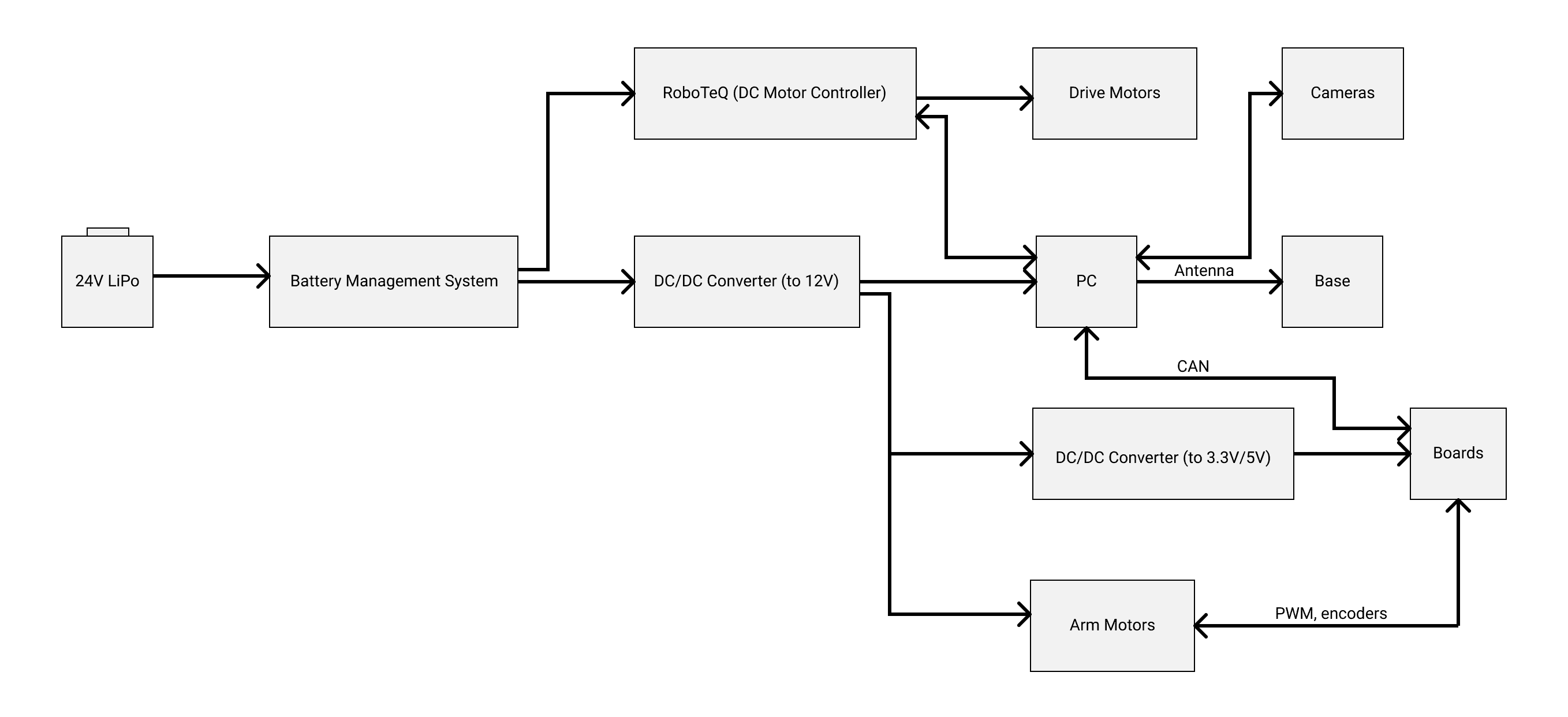
System Block Diagram

—Control Boards

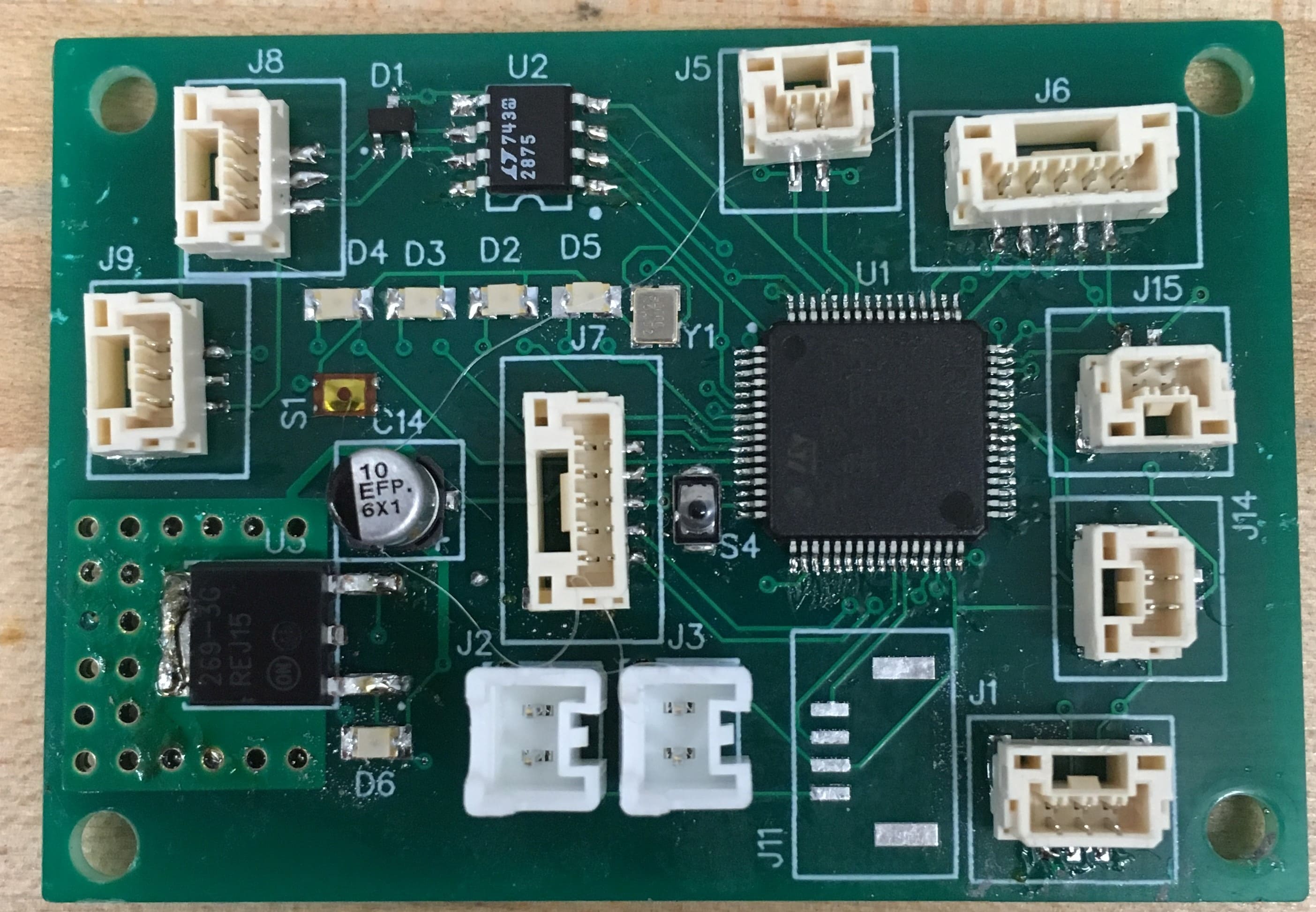
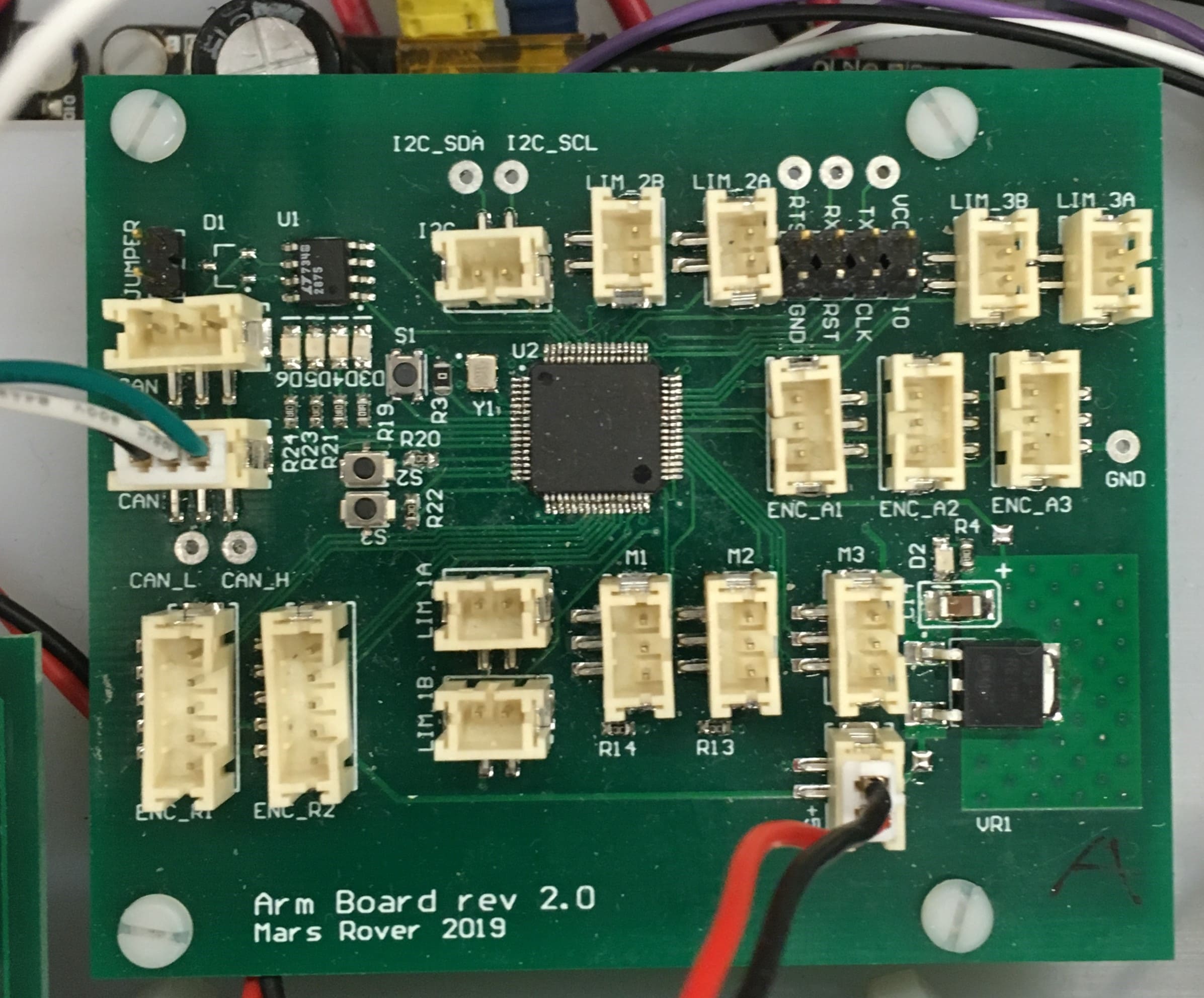
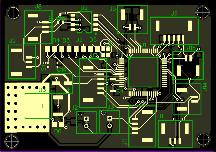
We design, bring-up, and test our own custom control boards for the rover. Personally, I designed the schematic and layout for the 2018 end effector board, the schematic for the 2019 safety board, and the schematic and layout for the 2019 arm board.

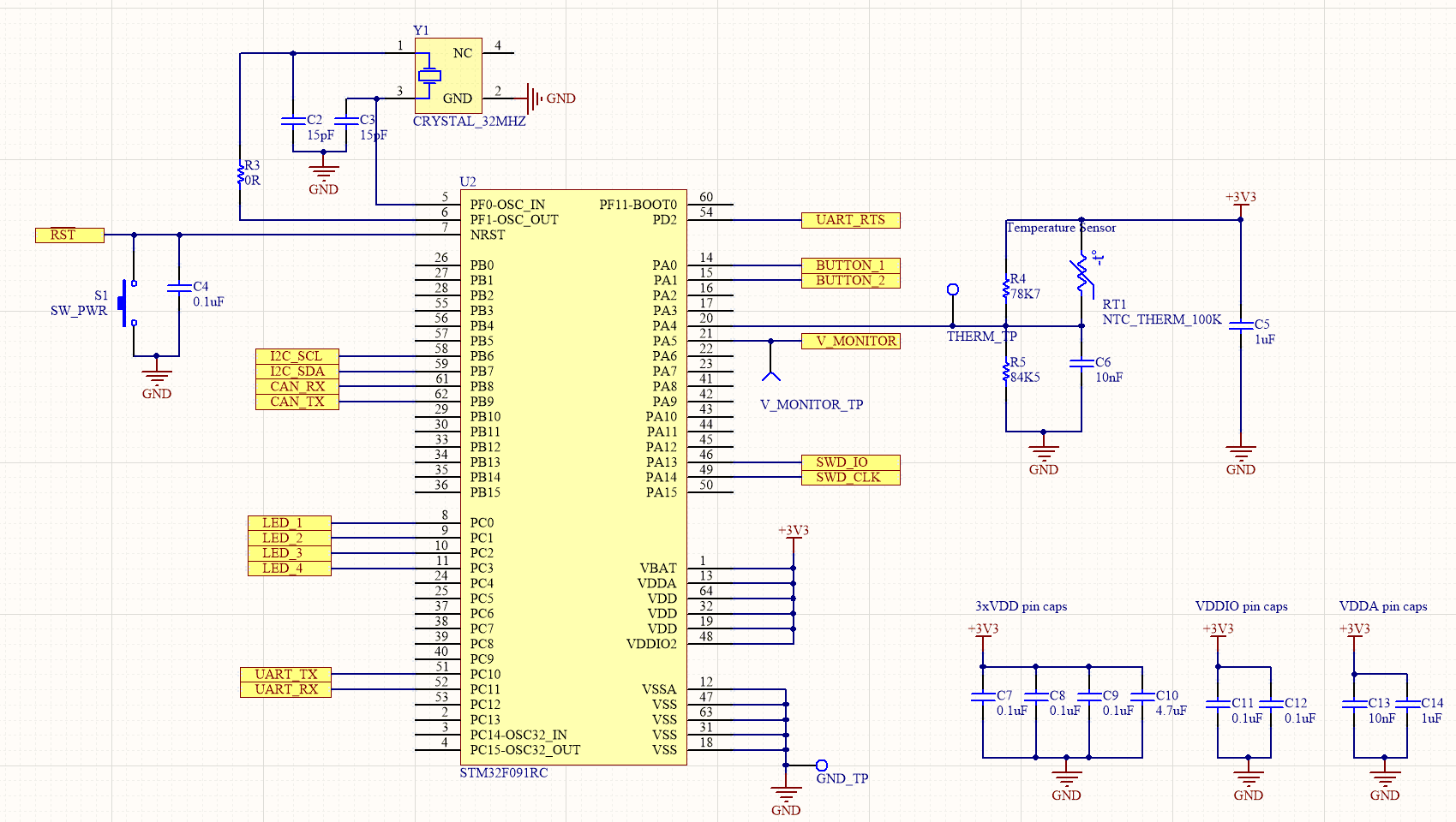
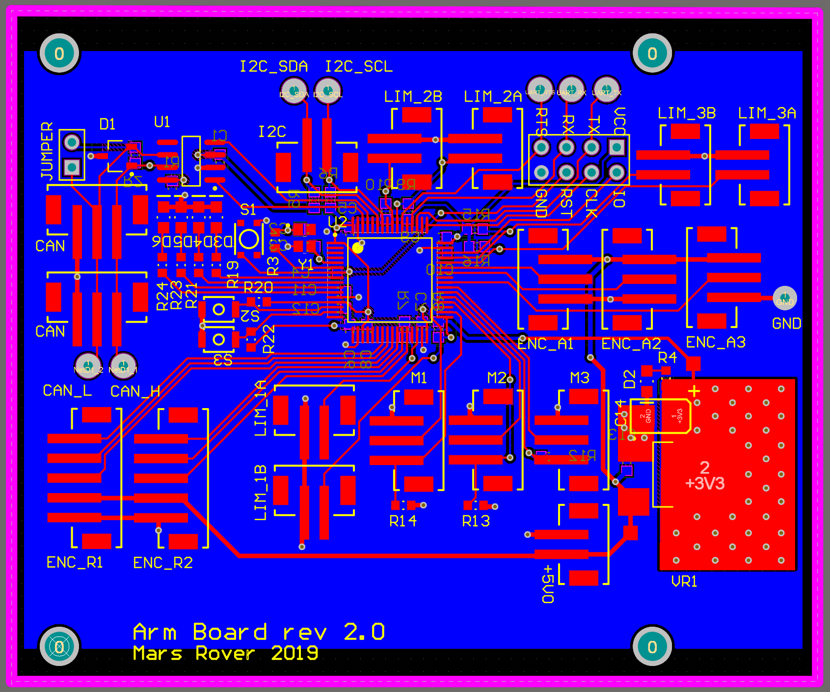
See full schematics and PCB layouts →

When designing the boards, I aimed to minimize noise by keeping PWM signals far from communication signals, and I used a copper pour with vias around the voltage regulator for thermal relief.

End Effector Board

Functions: Control 2 wrist motors, read limit switch and encoder signals from wrist, use CAN to communicate with Jetson

Safety board

Functions: Monitor temperature in electrical box using NTC thermistor, monitor battery level, read current sensor values over I2C, communicate with Jetson over CAN

Arm board

Functions: Control 3 arm motors, read arm encoders and limit switch signals, use CAN to communicate with the Jetson

—Power Distribution

In the 2018 design season, we used a 24V battery to power the drive motors, a 12V battery for the PC, and a 12V battery for the arm motors and custom boards. This solution was heavy, and put us over our weight limitations at competition last year.

This year, we opted for a solution with one 24V battery and a 24V/12V step-down converter to power the Jetson and the arm motors. We also have a 12V/5V converter to step down the voltage for the custom control boards.

It appears you don't have a PDF plugin for this browser. You can click here to download the PDF file.

—Science

The main purpose of the science task is to determine if life is extinct or extant by analyzing rock and soil samples, and the temperature and moisture levels of the soil. As part of competition rules for this year, all science tasks need to be conducted on the rover.

I oversaw the selection of sensors for the rover:

  • Moisture Sensor: Read the moisture levels in the soil in the hole dug by the auger
  • Temperature Sensor: Read the temperature of the soil in the hole dug by the auger
  • RGB Sensor: Determine levels of nitrates and phosphates based on the shade of the colour

—Wireless Comms

A member of the team lead the research and selection of the wireless communications. We use the 900MHz band for controls and data (to/from the Jetson to control the rover) and the 2.4GHz band for the video feed, mainly for the science task.

900 MHz

On the base station side, we have a Ubiquiti Rocket M900 for the router, and an omnidirectional antenna, the HGV-906U.

On the rover side, we have a Ubiquiti Rocket M900 for the router, and an omnidirectional antenna, a Bluebeam Ultra MadMushroom

2.4GHz

On the base station side, we have a 2.4GHz directional antenna and a 2.4GHz commercial router/modem.

On the rover side, we have a 2.4GHz omnidirectional rubber duck antenna and a 2.4GHz commercial router/modem.

—URC 2019

We will be competing at the end of May/beginning of June alongside 35 other teams :)