back back

—Inductive Charger

I designed and built an inductive charging system for a phone that does not natively support wireless charging.

Tools: Altium Designer, LTSpice, Oscilloscope

Keywords: flyback converter, wireless transmitter/receiver, LC oscillator

—Inspiration

I have an old iPhone SE from 2015 and I feel left out from the simplicity and ease of wireless charging. I wanted to design a system so I could pretend like my phone has wireless charging.

To do this, I can mount the receiver to the back of my phone and connect the output to a wired charging cable. My design is spec'ed to allow 500mA charging at 5V.

Power flow diagram for inductive charger:
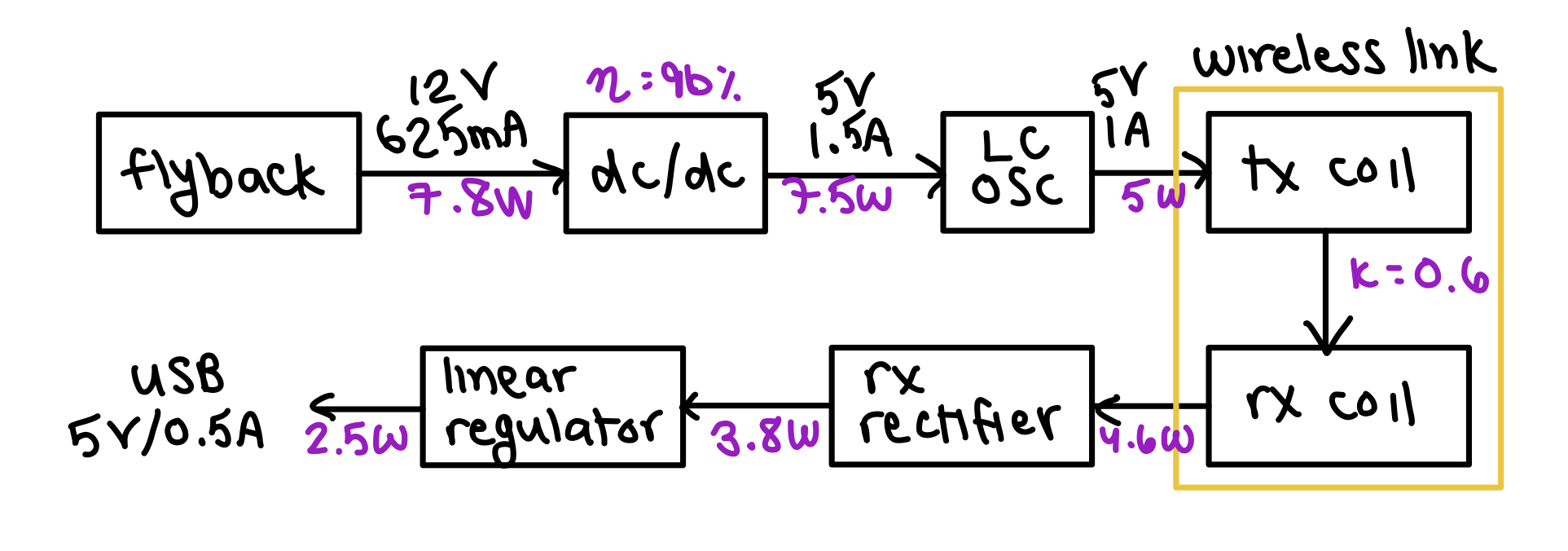
Based on simulation and calculation

I designed each block independently, and worked backwards from load to specify power requirements and tune/bias circuits.
—Wireless Link

Starting with the heart of the circuit: the wireless link. Since the receiver (connected to the phone) will only be used with one transmitter, the simplest way to transmit power is at a set frequency with magnetic resonant charging.

Since it's at a fixed frequency and fixed power output, I decided to design the circuits without use of transmitter or receiver ICs (definitely NOT Qi-compatible).

Principle of Operation

Wireless charging is inherently less efficient (50% to 70%) than wired charging (80% to 98%). As a result, it is desirable to couple the coils in such a way that the maximum amount of energy can be transferred. Magnetic resonant coupling relies on an oscillating magnetic field to couple magnetic energy between two coils operating at the same resonant freqency. This is less efficient if the system needs to be compatible across a wide range of transmitters/receivers, but more efficient for a single TX/RX combination (and allows for efficient transmission without precise mechanical alignment).

    Key parameters:
  • Q-factor: Maximize TX Q-factor (wo*L/R) to minimize loss in transmission
  • Coil geometry: Maximum coupling coefficient (k) when TX and RX coils are the same size
  • Turns ratio: Higher turns ratio to maximize magnetic energy can be coupled to the receiver
  • DC Resistance: Minimize DC resistance to reduce losses
Wurth Electronics WPT Design Tool

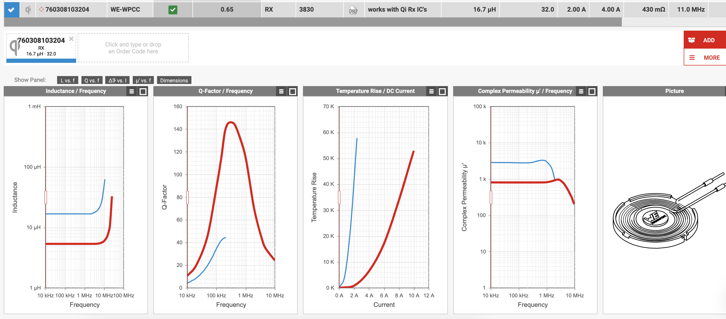
Keeping the key parameters in mind, I used the WE wireless power transfer design tool to choose a compatible combination of coils.

TX/RX Coil compatibility based on size, Q-factor, and coupling coefficient

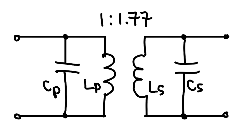
I chose the following coils (n=1.77 and k=0.65):

To acheive a resonant frequency of 100kHz, I set Cp = 0.47uF and Cs=0.1uF (detune secondary side below 100kHz to prevent overcoupling).

—LC Oscillator

After sourcing the coils, I designed the TX oscillator. The resonator needs to: be able to source enough current (around 2A) to drive the TX coil, is driven by a single DC supply, and needs to operate at the set resonant frequency (100kHz).

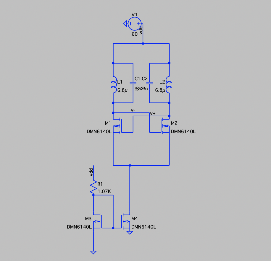
In this case, the first time I designed a cross-coupled LC oscillator with its own LC tank (image below). This didn't work because the signal needed to be buffered to prevent loading of the LC tank. This limited the amplitude of the signal, as well as the current that could be sourced from the supply.

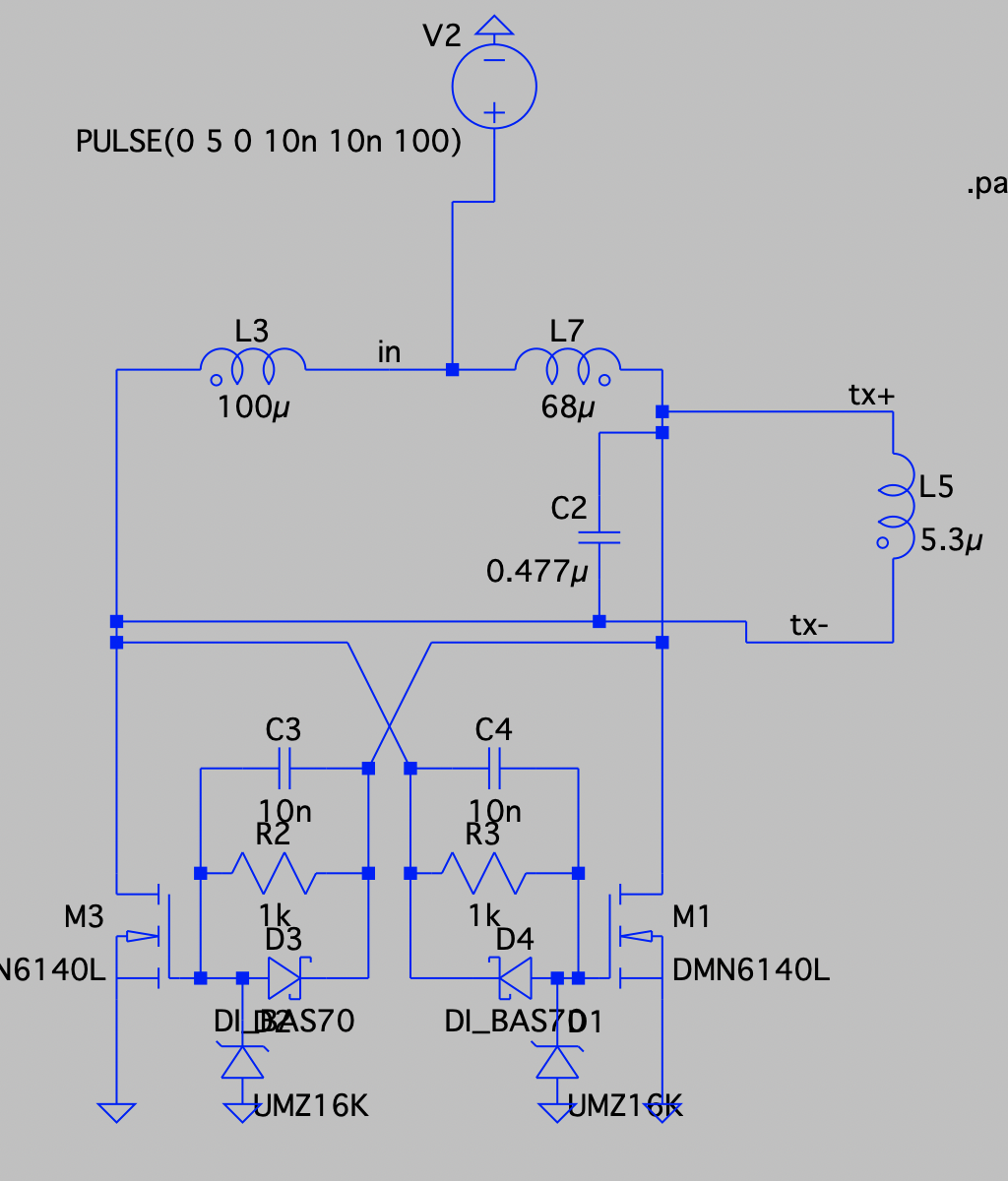
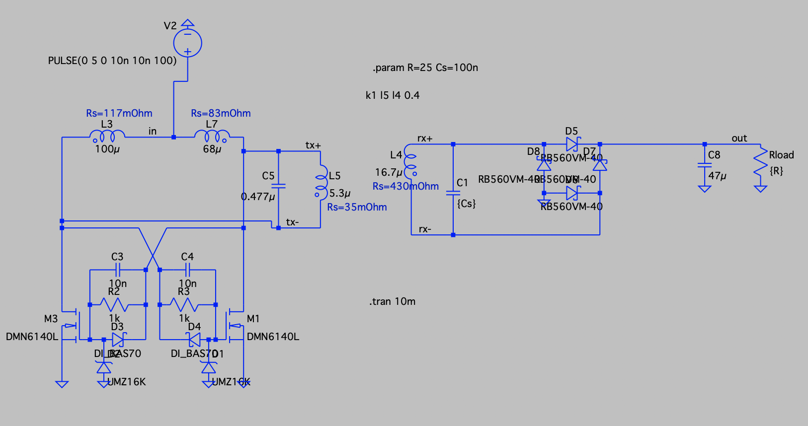
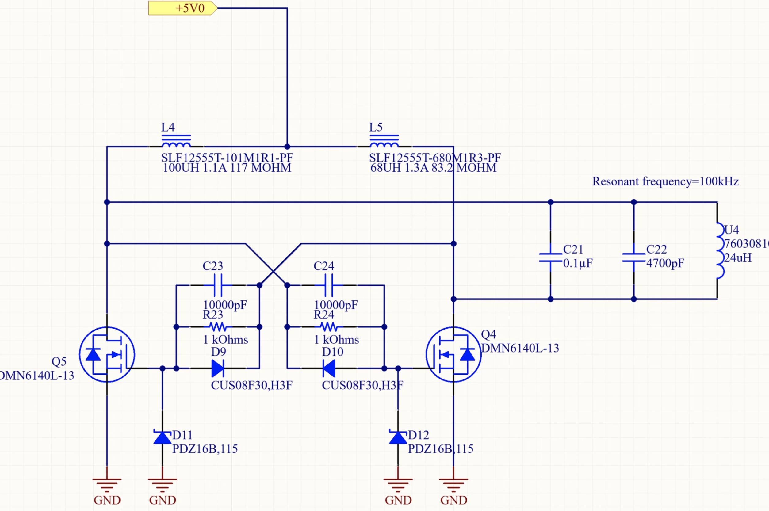
To solve this issue, inspired by an wireless charging application note by Analog Devices, I designed a cross-coupled LC oscillator that used the TX coiil as the resonant inductor.

Principle of Operation

This push-pull current-fed resonator drives the LC tank with two MOSFETs: Since the gate of each FET is tied to the drain of the other, when one FET turns on it will turn off the other fet. The zener diode at the gate limits the gate voltage and prevents damage to the FET, and the RLD snubber improves the turn off speed of the MOSFETs.

—RX Regulation

Once the TX oscillator was designed, I had a better idea of the input power, voltage/current specifications, and efficiency of the system. At this point I designed the rectifier and regulation at the receiver. I used a full-bridge rectifier connected to a linear regulator, which goes to a USB connector.

—Input power regulation

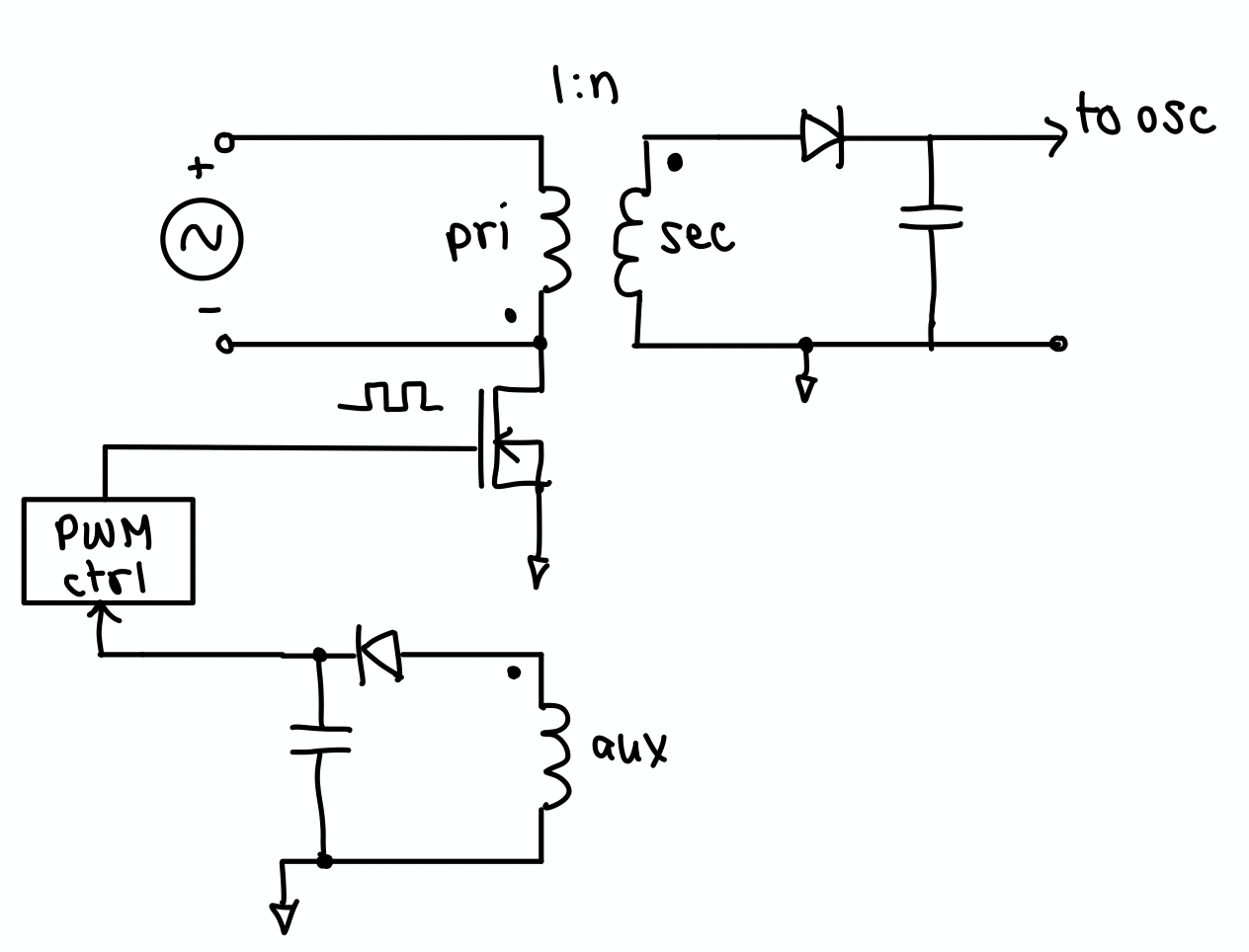
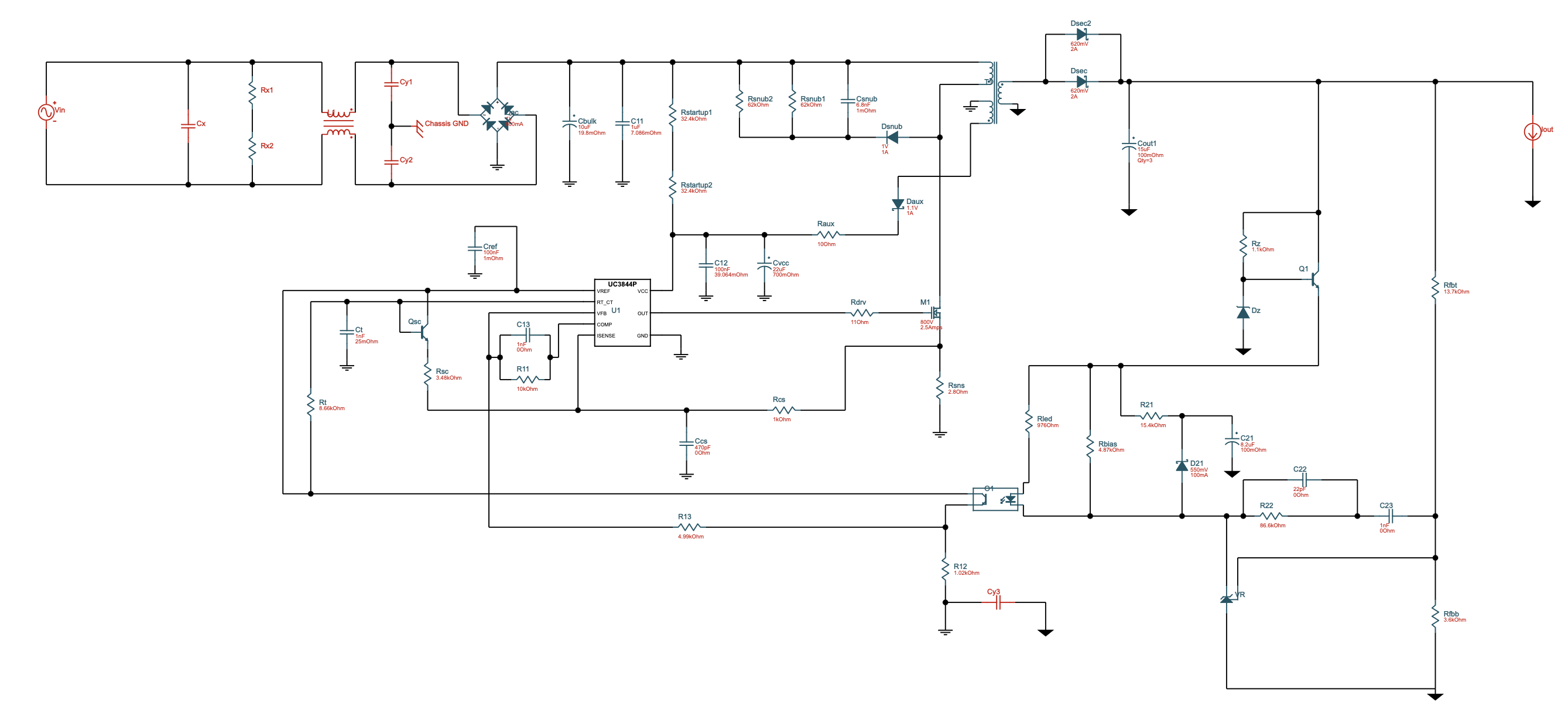
In addition to the design of the wireless converter, I thought it would be fun to design the offline AC/DC converter to provide the best efficiency and customization for my system. Originally, I attempted to design a discrete DCM flyback regulator (block diagram below).

The issue that I ran into was the auxiliary winding (which would provide power to the PWM controller to drive the FET) required output power to turn on, but the FET needs the input from the PWM to start driving the coil. As a result, I realized that it would require an IC and more complicated circuitry (including soft-start). So instead, I used the Texas Instruments Webench tool to design the converter.

One of the difficult parts of the design is sourcing the coil. Since it is intended to meet specific power requirements, TI recommends the use of a custom coil. So I sourced a coil from Wurth Electronics that met the frequency, inductance, and output power requirements of the converter. Since the coil is spec'ed for a fixed output voltage, I fed the output of the flyback converter to a DC/DC converter to get the correct voltage for my oscillator.

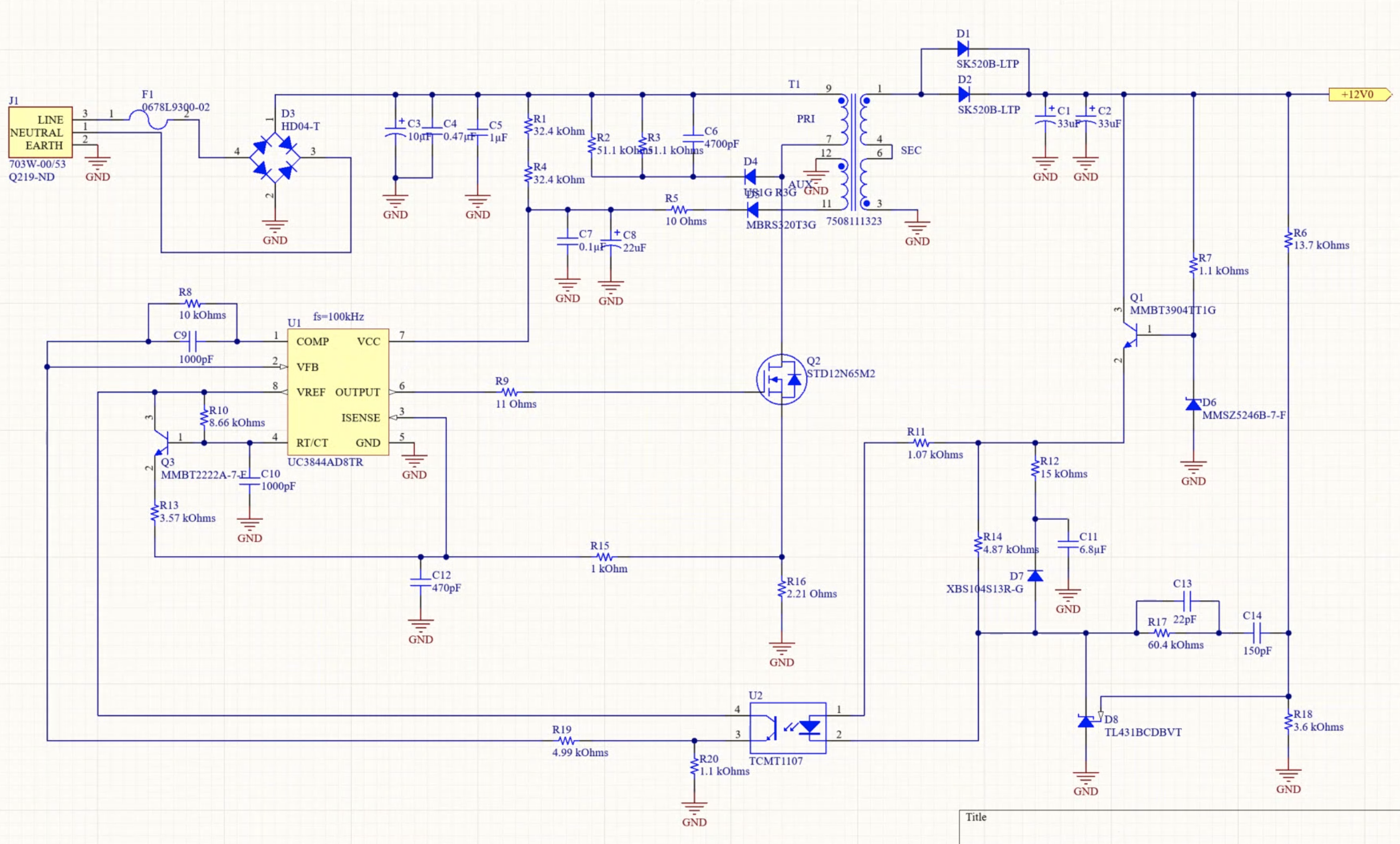
This converter operates at a frequency of 100kHz with 80% efficiency, and the output voltage is 12V. This circuit feeds rectified AC power to the coil, which is switched at a fixed frequency by the MOSFET (driven by the UC3844).

Optocoupler Feedback

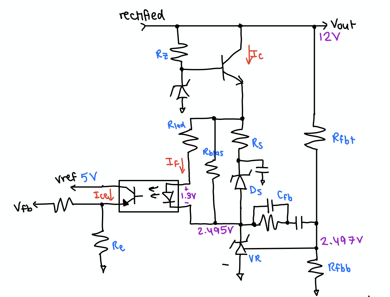
To keep the output isolated from mains, I used an optocoupler with a TL431 shunt regulator for feedback to the controller. When the voltage at the output increases, the reference voltage to the TL431 will also increase. This will cause the shunt regulator to source more current, thereby increasing the current through the photodiode. A higher current through the photodiode means that there will be a higher Ice on the output, and a lower voltage at the feedback pin. The controller can then decrease the switching frequency.

DC/DC Converter

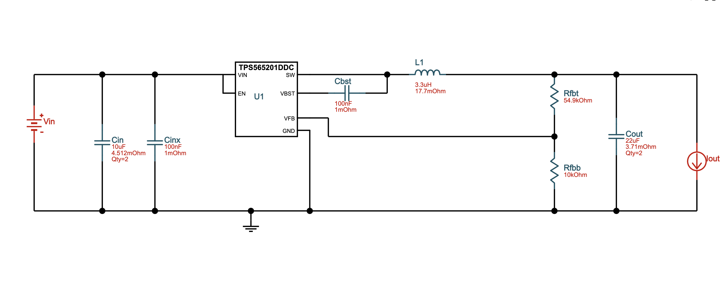
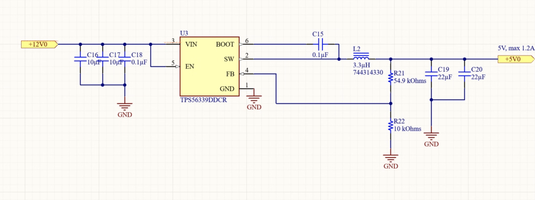
The flyback converter outputs 12V/0.5A, and the input to the TX oscillator should be 5V. So I added a DC/DC converter (also using TI Webench) to do the conversion.

—Simulations

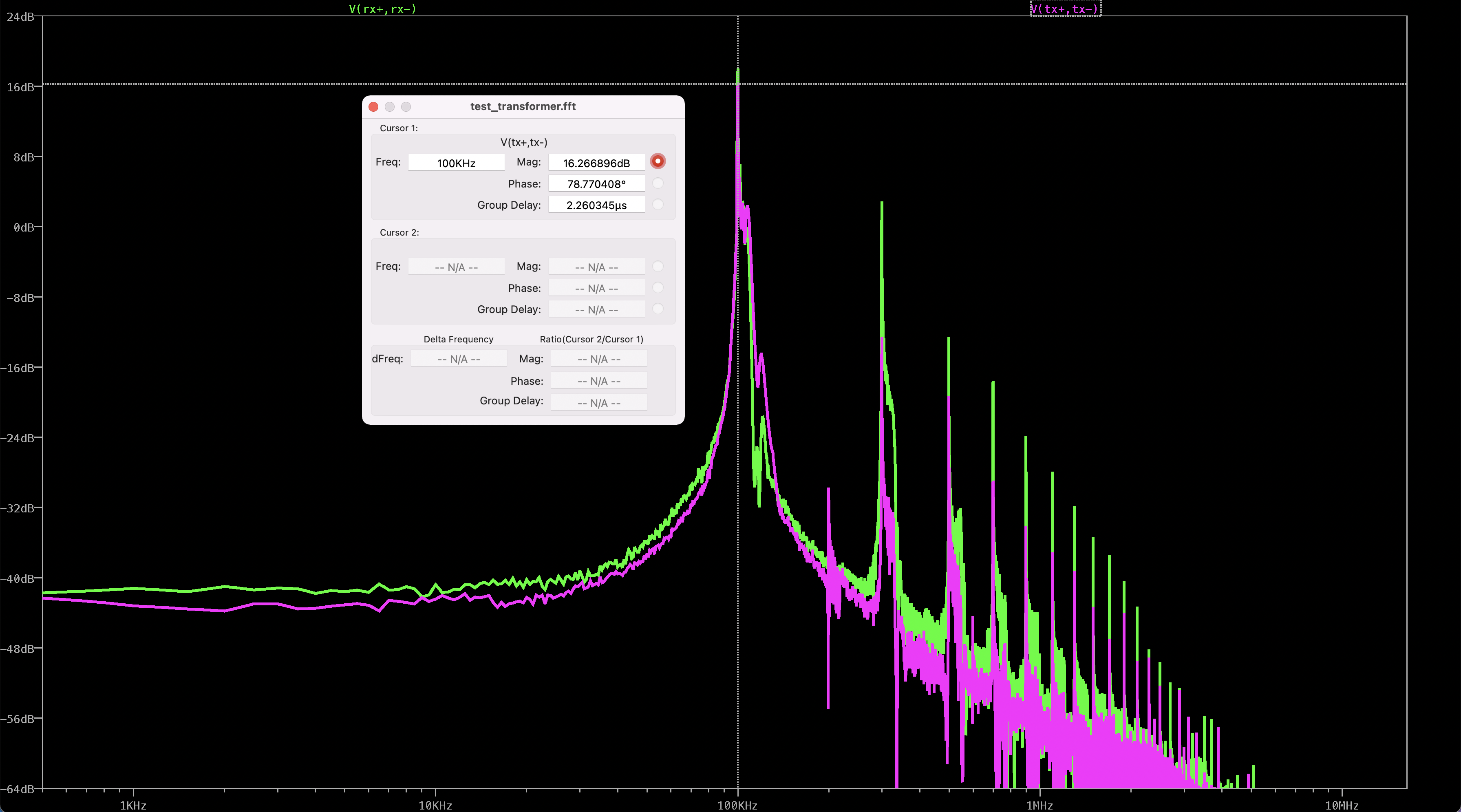
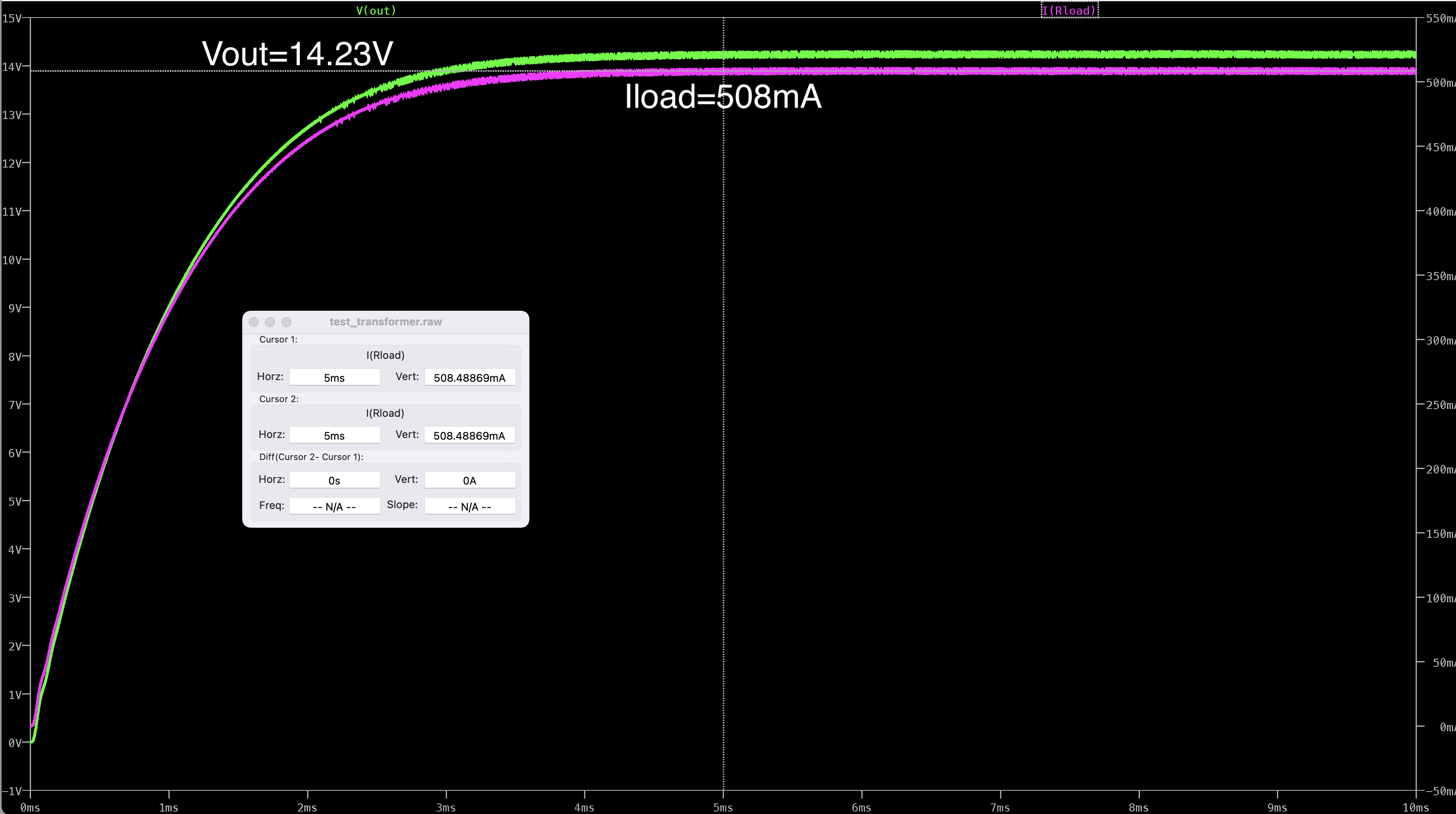
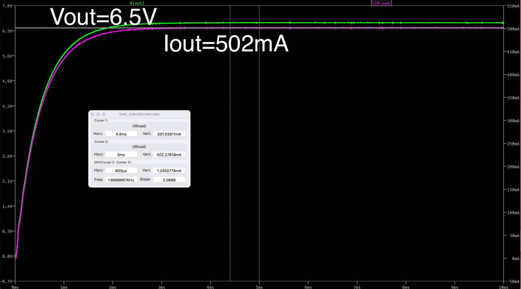
I ran simulations in LTSpice to ensure that the wireless charger operated as intended. Even though the coupling coefficient on Wurth Electronic's tool was 0.65, I tested with 0.4 to ensure that even if the alignment was not ideal that the circuit would still function as expected.

FFT of TX frequency and RX frequency

With the secondary frequency set to resonance, it maximizes the output power. Since the output from the regulator should be 5V/500mA, I can adjust the secondary resonant capacitor to set the output to the correct level.

Cs=100nF to set secondary frequency to 100kHz (resonance)
Cs=170nF to set output voltage to correct level

—Final Schematics

I designed the schematics in Altium:

Discontinous-mode flyback converter (120V to 12V)
12V-5V buck converter
LC oscillator and TX coil
RX coil and USB output

—Board Layout

Work in progress...